
 Enschede
In 2018, I stumbled upon an article about the RTL-SDR dongle. For the uninitiated, the RTL-SDR is a software defined radio receiver that uses a Realtek RTL2832U chipset. An SDR is basically a radio communication system where components that have been traditionally implemented in hardware are instead implemented by means of software on a personal computer or embedded system. I of course had to get my hands on one of these dongles and start playing with it. My kit came with some basic dipole antennas that I used with RTL-SDR’s tutorials to grab FM radio and ham-radio signals and get boat and aircraft tracking data. This was essentially my first step into the hobby of amateur radio.
Weather Satellites
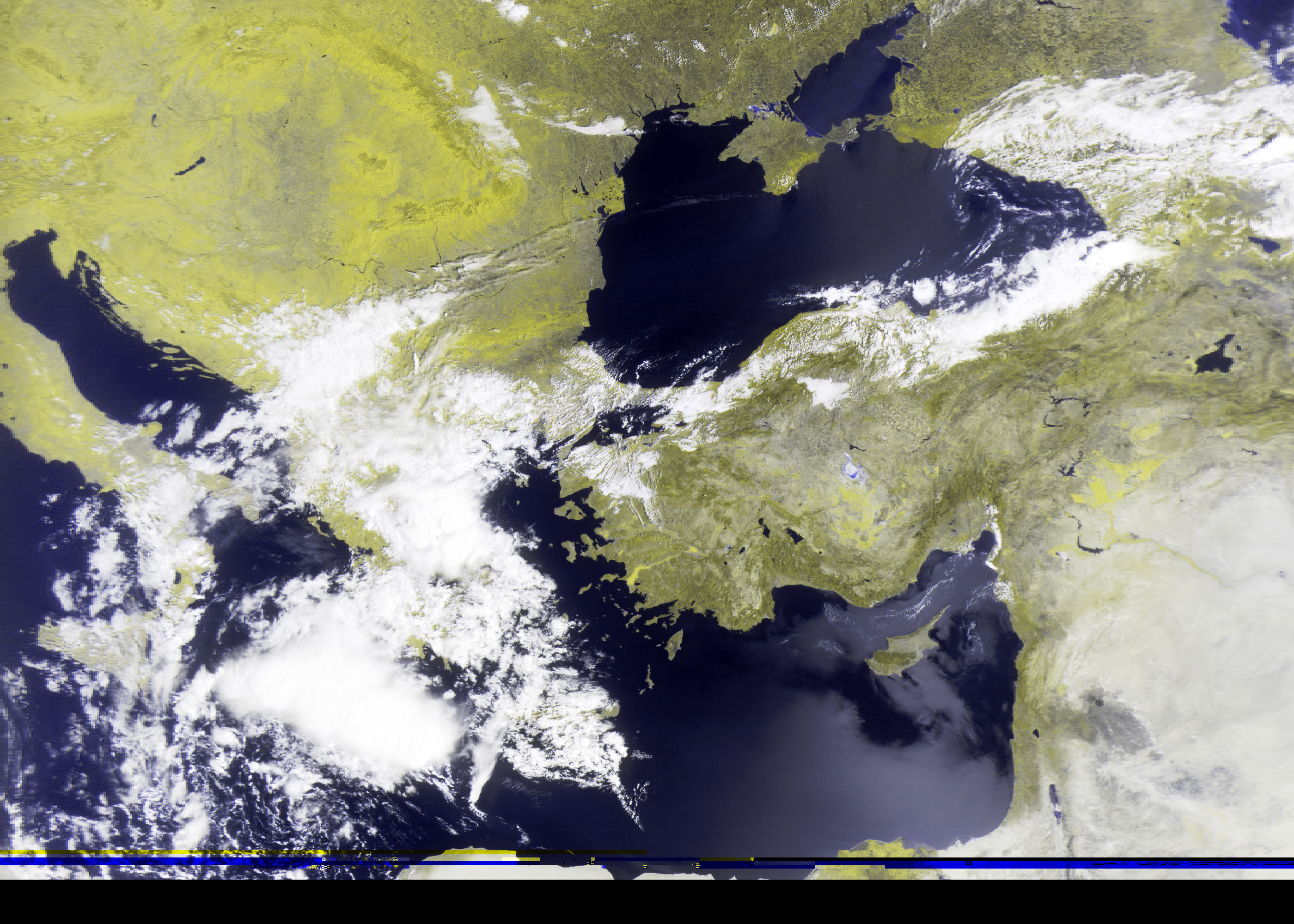
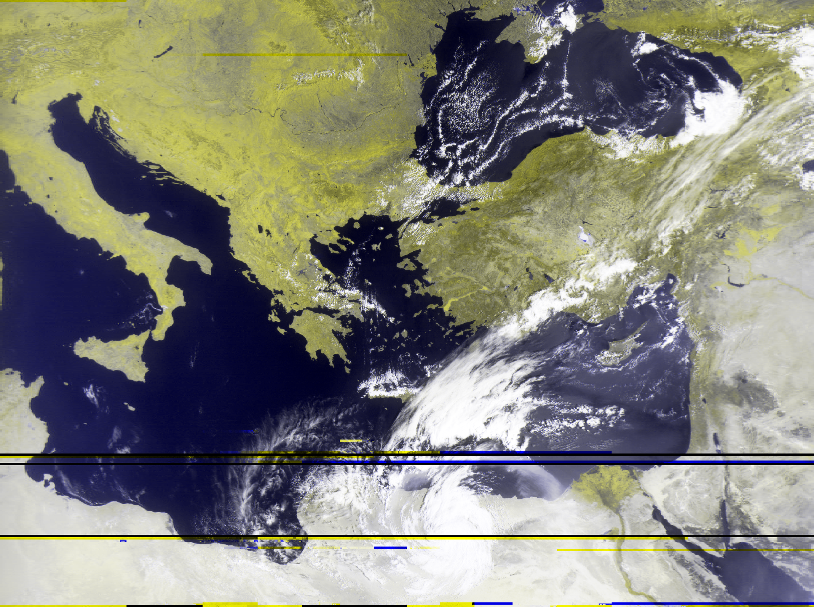
The next goal was satellite signal reception, but the dipole antennas were simply not getting the job done, even though people have been successful on using them in a certain configuration. The “Hello World” of satellite reception is the NOAA weather satellites, namely the NOAA 15, 18, and 19. These sats transmit APT (Automatic Picture Transmission), an analog image transmission system that transmits two channels of image data in the 137 MHz band. They move in a sun-synchronous orbit, which means they pass over the (approximately…) same location at the same time every day (…approximately).
Another popular satellite is the Russian Meteor-M2. It is a more modern satellite that transmits digital images in the 137 MHz band using a method called LRPT (Low-rate Picture Transmission). The images are of higher resolution and quality than the NOAA satellites, but the downside is that the signal is more difficult to decode. In all other aspects, the Meteor-M2 is similar to the NOAA satellites.
To track these satellites and find what time they will pass over your location you can use satellite tracking software such as Orbitron or GPredict. There is also an amazing website by N2YO that provides real-time tracking of satellites and has some info on the frequences they transmit on. Meteor M2-3 and M2-4 satellites transmit on 137.9000 MHz but are known to change their frequencies, so you can check if the latest information is available here. For the NOAA satellites, the frequencies are 137.6200 MHz for NOAA 15, 137.9125 MHz for NOAA 18, and 137.1000 MHz for NOAA 19.
Quadrifilar Helix Antenna
The reason why many common antennas, like dipoles, are not suitable for satellite reception is that they are linearly polarized. Polarization is the orientation of the electric field of the radio wave in 3D space. In linear polarization, the electric and magnetic fields exist on static planes. By aligning the receiving antenna with the transmitting antenna, the signal strength is maximized. However, satellite signals are circularly polarized, which means that the electric field rotates in a circular pattern. This means that special antennas are needed to receive these signals that are called circularly polarized antennas. It is also important to note that the direction of the rotation can be either right-hand (RHCP) or left-hand (LHCP) circularly polarized. NOAA and Meteor-M2 satellites transmit with RHCP polarization on the 137 MHz band.
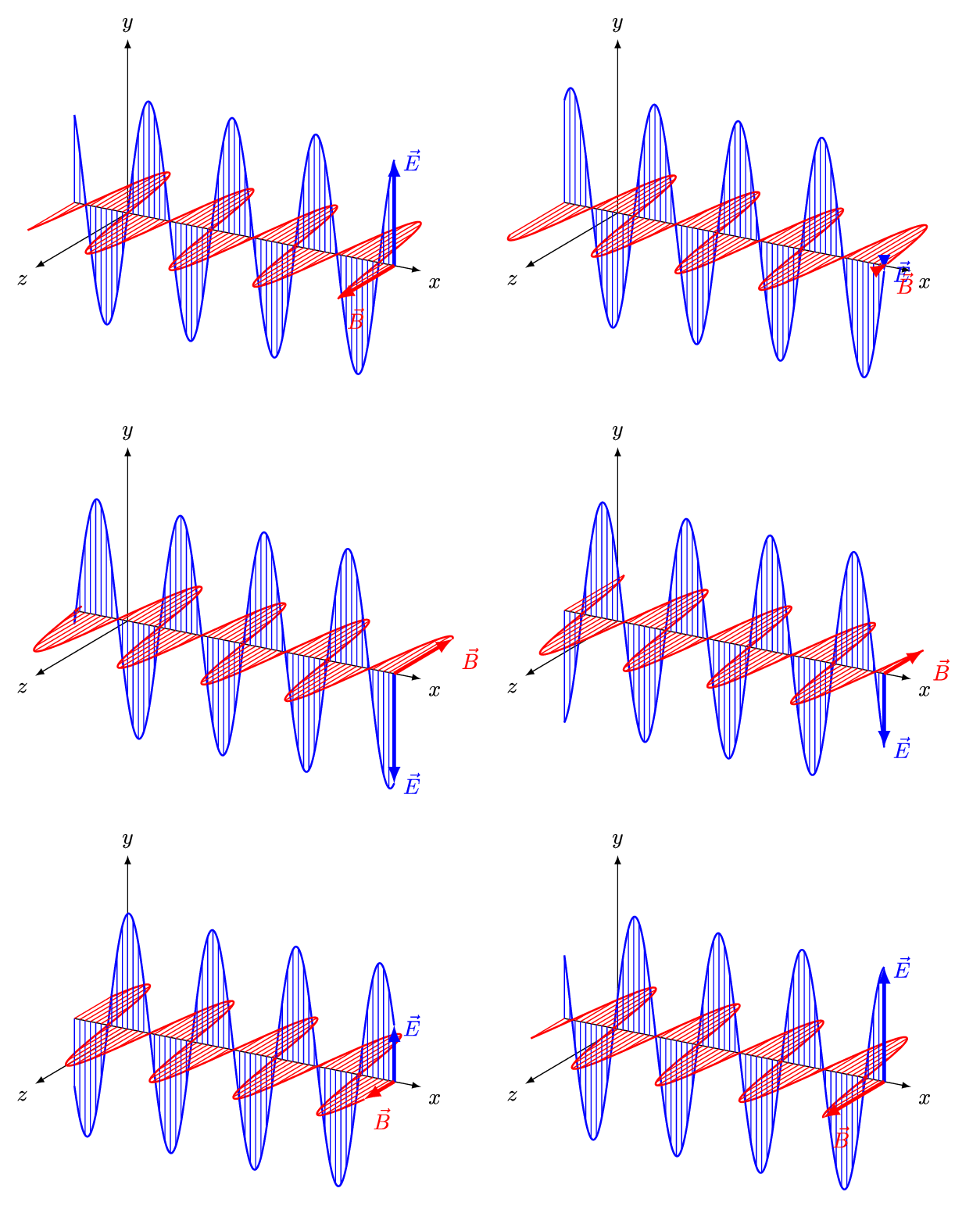
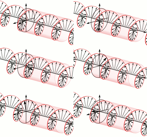
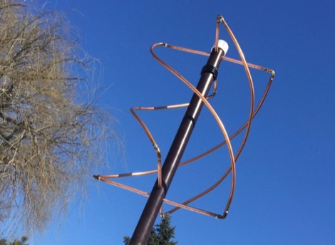
Most articles and tutorials about weather satellite reception recommend the Quadrifilar Helix Antenna (QFH). It is not the easiest antenna to build, but supposedly it is very good for this kind of satellite reception and it can have a wide bandwidth which means that it is forgiving in terms of tuning. The QFH consists of two loops that are wound in a helix around a central support. The dimensions of the loops are critical and must be calculated based on the frequency of the satellite signal. The direction of the helix is also important, as it determines if the antenna is right-hand or left-hand circularly polarized.
The Build
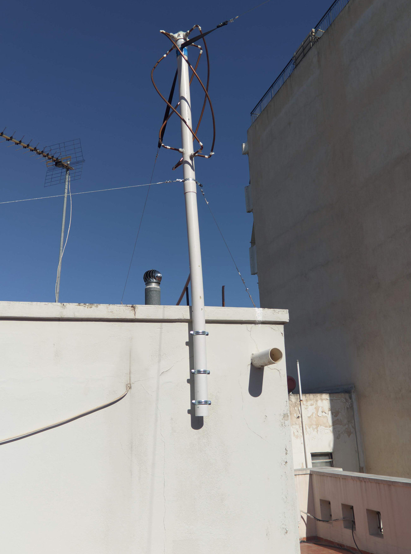
Unfortunately, I did not document the build process of my QFH antenna in detail. The mast was made from a PVC pipe, and the antenna elements were made from soft copper pipe. The dimensions of the loops were calculated using this online calculator. I based my design on other people’s work, and I used a combination of different designs to come up with my own. I will not attempt to provide any blueprints here since I did not come up with the design myself, so do read the articles linked in the Further Reading section for more information.
Antenna Elements & Mast
To begin with, I cut pieces of the copper pipe to the calculated lengths for the straight elements on the top and bottom of the loops. I used a circular electrical box to secure the top elements and allow for the connection of the coaxial cable. Waterproof electrical pass-throughs were used to secure the elements to the electrical box. The ends of the top elements were cut in a 45° angle to allow for a better connection to the larger, bent parts of the loops.
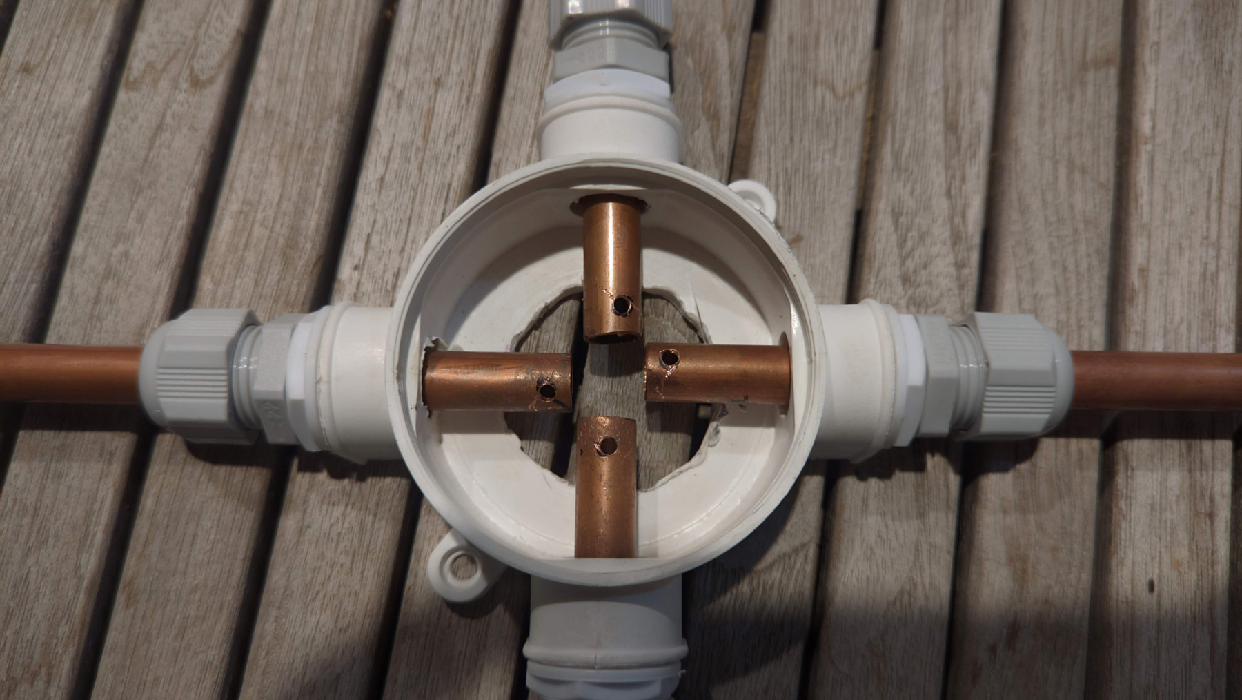
Slots were cut in the PVC pipe to allow for the insertion of the top elements.
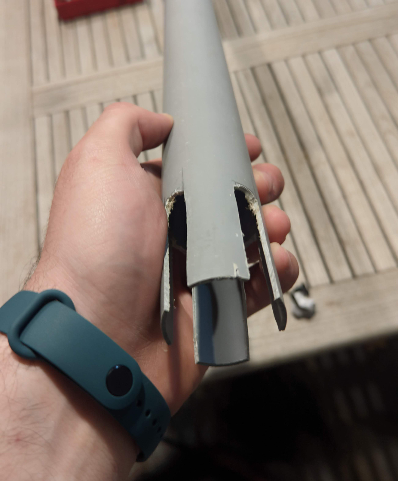
Similar pass-throughs were used to secure the bottom elements to the PVC pipe in the appropriate positions. Attention should be paid on the 45° angle of the bottom elements, as they need to be in a 90° offset on the opposite side of each element. This is also true for the top elements, but the two ends are separate there and can be rotated independently.
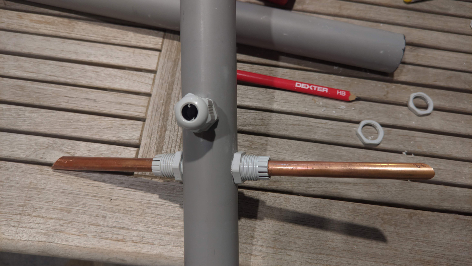
The four large, bent elements were cut in appropriate lengths and bent to a semi-circle. The ends were once again cut in a 45° angle to allow for a better connection to the top and bottom elements. Plumbing solder and a blowtorch was used to make the connections with the bottom elements. The large elements were then bent from a semi-circle to a helix around the PVC pipe to attach to the top elements and soldered in place.
Coaxial Cable & Balun
A length of 50Ohm coaxial cable was soldered to the top elements according to the blueprints.
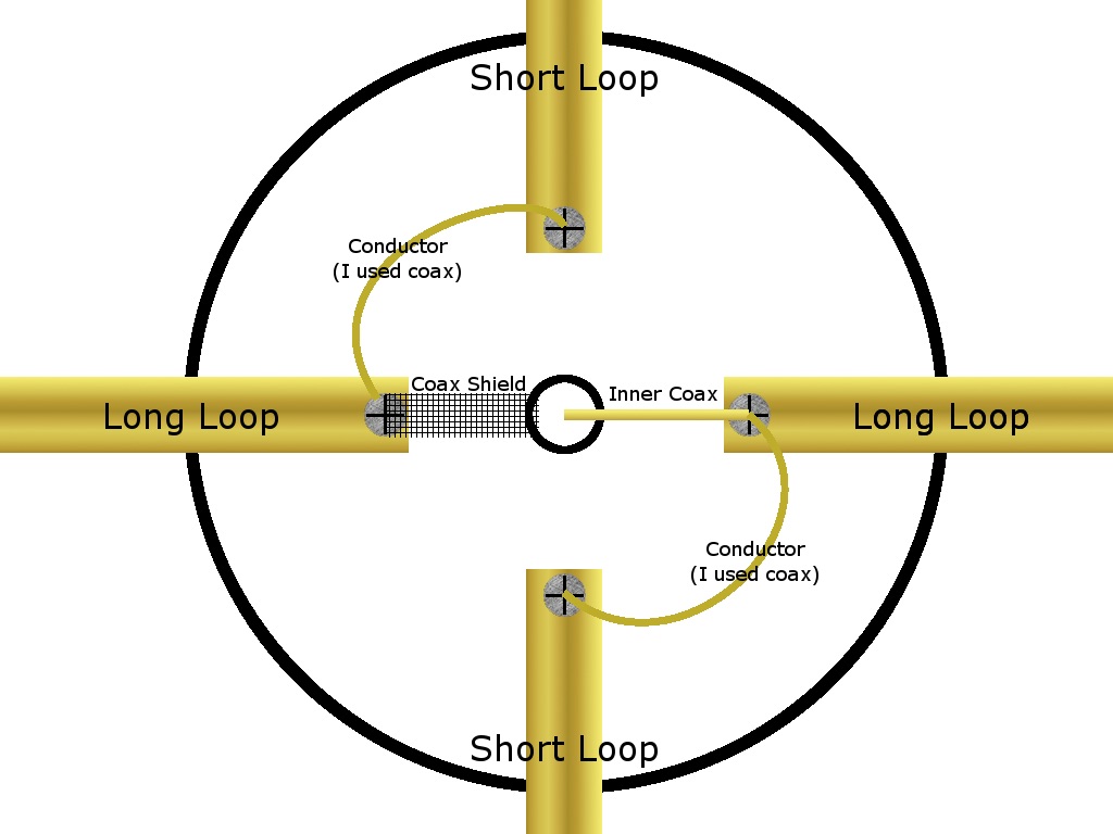 Source: A QFH design by K6KZO
Right under the top elements, a hole was drilled in the PVC pipe to allow for the coaxial cable to pass through. The coaxial was then looped 4 times around the PVC pipe to act as a balun. Another hole was drilled below the balun to allow for the coax to go back inside the mast pip and exit at the bottom.
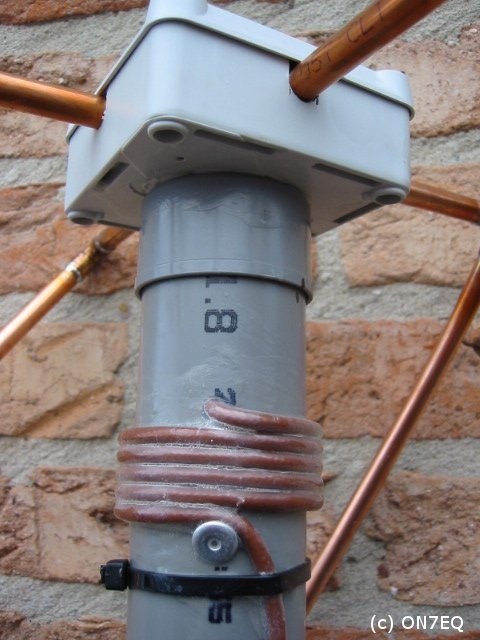
Source: A QFH design by ON7EQ
Mounting
To waterproof the antenna I used sealing silicone to fill the electrical box on the top and holes for the coaxial cable in the PVC pipe. The mast was secured on the wall on my roof using pipe clamps. Steel wire was attached at four points on the antenna, two on the top and two on the base of the antenna. The wire was then attached on the roof and tightened to secure the antenna against the wind.
Results




Comments